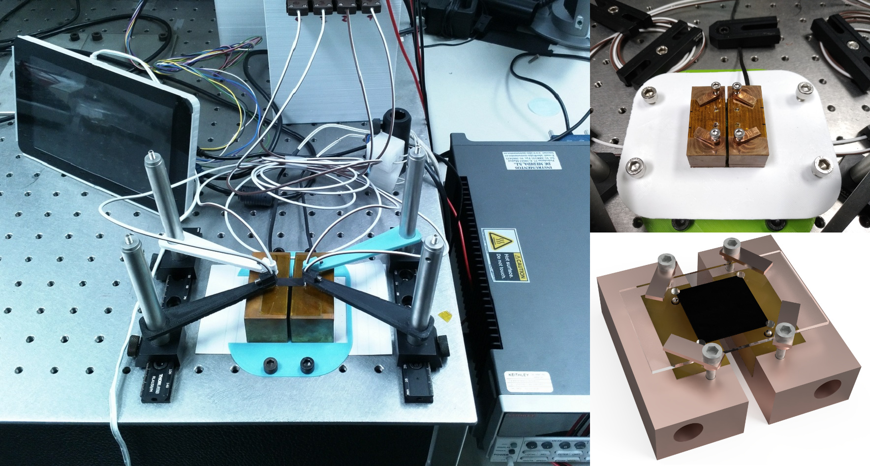
Setup explanation:
- The sheet resistance is determined using the van der Pauw method, by measuring all permutations of 4-point resistances between pairs of corners on the sample.
- For anisotropic samples, both in-plane components of the electrical conductivity (σx, σy) are determined according to a method proposed by Price.
- The Seebeck coefficient is obtained by heating one side of the sample and fitting the slope of the measured thermovoltage versus the applied temperature difference. By turning the sample by 90°, both in-plane components of the Seebeck coefficient (Sx, Sy) can be measured.
- Resistances and thermovoltage are measured using the copper strands of the four T type thermocouples, while the local temperatures are measured using the copper and constantan strands of each individual thermocouple.
- Data are acquired using a Keithley 2400 SourceMeter that is controlled via GPIB by aRaspberry Pi single-board computer.
- Different sampleholder can be used for free-standing, or glass-supported samplesrespectively.
For further details on the setup and methodology, see the article: “A setup to measure the Seebeck coefficient and electrical conductivity of anisotropic thin-films on a single sample“
References:
- van der Pauw, L. J. A method of measuring the resistivity and Hall coefficent on lamellae of arbitrary shape. Philips Tech. Rev. 20, 220–224 (1958).
- Price, W. L. V. Electric potential and current distribution in a rectangular sample of anisotropic material with application to the measurement of the principal resistivities by an extension of van der Pauw’s method. Solid. State. Electron. 16, 753–762 (1973).
Lab: Optical Lab
Contact: Bernhard Dörling (bdorling@icmab.es)